XY Cutter
  • 2-Axis
  • Used in Cutting CNC machines
xy20cutter20photo
XY Cutter
  • 2-Axis
  • Used in Cutting CNC machines

Introduction

Plasma cutting is a thermal-machining process: a pressurised gas stream (oxygen, nitrogen, or compressed air) is ionised inside the torch and becomes a high-temperature plasma column. The arc melts the metal; the same jet ejects the molten material at high velocity, leaving a narrow kerf. In a CNC system the torch path — and its live height correction — is driven automatically in the X and Y axes, and, when required, a Z axis. Computer control (G-code) replaces manual hand-guiding and delivers repeatable accuracy.

Mechanical Layer

A lightweight gantry rides on linear rails and positions the torch in X–Y.
When constant standoff or deeper operations are needed, a Z axis is added.
The Z drive may be a servo, stepper, or simple DC motor; in every case it must accept an up/down command from the controller to keep the torch-to-work distance stable.

Hardware Layer

The hardware configuration depends primarily on the Z-axis drive type. Two controller options are recommended based on whether a third motor and additional digital I/Os are required: PC-Smart 4A /PC-ProLAN 4A and PC-Smart 3AS. 

RADONIX controllers operate on a Pulse and Direction basis in the axis control section.

Untitled design 2025 07 12T015349.626

Software Layer

The Radonix 2D Cutting Interface serves as the operator’s central hub, bridging the design file and the CNC controller. It consolidates all setup, monitoring, and execution functions into one intuitive environment to simplify operations and improve efficiency.

Key Features of Radonix CNC Software

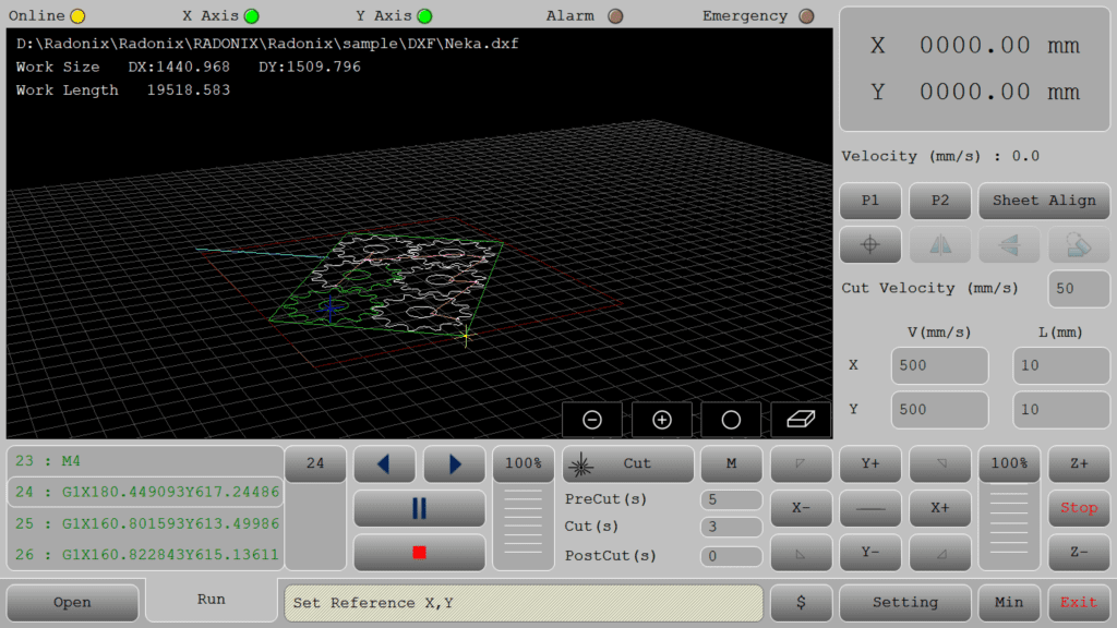
🔹 Direct DXF Execution

Seamlessly load and execute DXF files without the need for G-code conversion — streamlining your workflow and reducing setup time.

🔹 Smart Component & Path Management

Select specific parts from complex drawings and customize cutting order with intuitive control over toolpath sequencing.

🔹 Interactive On-Screen Editing

Scale, rotate, and mirror parts directly within the interface — with live toolpath previews to ensure precision.

🔹 Flexible Part Placement

Manually drag and drop parts onto your material sheet to accommodate irregular shapes, pre-cut stock, or remnant reuse.

🔹 Advanced Pause Controls

Set up to three independent pause points — before the cut, during the cut, and after the cut — for manual checks or operational adjustments.

🔹 Reverse Cutting Mode

Execute toolpaths in reverse to minimize material warping or adjust final exit points based on design needs.

🔹 Simulation / Demo Run Mode

Perform a complete motion test without activating the torch. Ideal for verifying the toolpath before live cutting.

🔹 Cylindrical Cutting Capability

Project flat designs onto cylindrical surfaces for precision tube and pipe cutting operations.

🔹 Live Arc-Voltage Monitoring

Real-time arc-voltage feedback ensures dynamic Z-axis height control — maintaining optimal torch-to-material distance during operation.

Conclusion

Once the drawing is loaded and adjusted within the interface, the job is sent over LAN — with X and Y axes driven by Pulse/Direction, and Z-axis controlled via high-speed pulses or simple digital toggles for basic DC drives.

Cutting takes place in real time, with arc-voltage feedback actively stabilizing the torch height, ensuring uniform edge quality throughout the process.

Upon completion, the system generates an automatic report, logging cycle time, total cut length, and pause events — offering valuable data for performance tracking and productivity analysis.

By integrating a robust mechanical frame, the Radonix motion controller, and an intelligent software layer, this solution delivers a tightly-synchronized workflow. It transforms digital designs into precise metal parts — with speed, accuracy, and full repeatability — built not on buzzwords, but on real engineering.

Radonix CNC Control Card – Hardware, Software, and Interface