
In 2025, a CNC Closed Loop System can push machine accuracy into the sub‑micron realm, unlocking capabilities that open‑loop setups cannot match. Whether you cut aerospace alloys, machine orthopedic implants, or hold ultra‑tight GD&T on prototype tooling, the control loop is your performance ceiling.
This guide explains what a CNC Closed Loop System is, how it works, and how to tune it for maximum repeatability and finish. We’ll compare closed‑loop vs open‑loop CNC behavior, walk through servo tuning CNC techniques, and show real‑world gains using Radonix closed‑loop controllers.
You’ll also see how encoder resolution, PID control in machining, and intelligent diagnostics create a high‑precision closed loop that’s stable under thermal drift and chatter.
For architectural background and HMI workflow, start with our primer: How CNC Controller Works: Full Guide to Precision Control on the Radonix blog, then evaluate hardware options at the Radonix closed-loop CNC controllers page.
How a CNC Closed Loop System Works: Feedback Fundamentals
A CNC Closed Loop System uses sensors to continuously measure actual position and velocity, comparing them to commanded trajectories and correcting errors in real time. This “measure–compare–correct” cycle is the essence of feedback in CNC systems.
Core components in the loop
- Motion control core: The CNC interpolator plans the path and issues position/velocity commands at a fixed servo rate (e.g., 1 kHz).
- Servo drives and motors: Drives close current and velocity loops on AC servos; motors deliver torque with high bandwidth.
- Encoders/resolvers: Linear or rotary devices provide absolute or incremental feedback; encoder resolution defines quantization and achievable control gain.
- I/O and PLC layer: Supervises safety and sequences; not part of the inner control loop but essential for dependable operation.
- HMI and diagnostics: Visualize following error, loop gains, and alarm history for faster tuning.
Feedback cycle at a glance
- Command: Interpolator outputs a target position for each axis at each servo tick.
- Execution: Drives produce torque; axis moves toward the target.
- Measurement: Encoders report actual position/velocity.
- Correction: Position loop computes error and applies control effort to reduce it on the next tick.
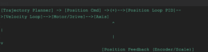
ASCII block diagram of a CNC Closed Loop System
Why it wins over open loop
- Closed loop detects load-induced errors and corrects them before they accumulate.
- Higher achievable accelerations and jerk control yield better surface finishes and shorter cycle times.
- Thermal and compliance compensation layers further elevate accuracy—cornerstones of high-precision closed-loop machining.
For controller families and cnc controller types beyond Radonix (e.g., Fanuc or Siemens), see Types of Controllers in CNC Machines Explained on our blog.
Precision Tuning Techniques for CNC Closed Loop Systems
The right gains transform a good machine into a great one. Below is a practical, step‑by‑step approach to tuning a CNC Closed Loop System safely and systematically.
Establish a safe baseline
- Start with conservative default gains from your drive vendor or Radonix presets.
- Verify mechanics first: backlash, loose couplings, and stick‑slip will sabotage any tuning.
Understand PID parameter basics
- P (proportional) attacks position error immediately—too high and it rings; too low and it feels soft.
- I (integral) removes steady‑state error—too high causes drift and overshoot.
- D (derivative) damps motion—too high amplifies noise; set after P is near‑optimal.
Increase P to stiffness, then add damping
- Jog and perform small step moves (e.g., 0.5 mm). Raise P until you see slight overshoot or oscillation, then back off 10–15%.
- Add D to remove ringing; increase until response is crisp without noise amplification.
Add I to kill residual error
- Command a constant velocity and hold; add I until steady‑state error goes near zero. Keep I modest to avoid sluggishness.
Optimize velocity/acceleration feedforward
- Use velocity and acceleration feedforward terms to reduce following error during ramps. This improves continuous path tracking.
Validate with real cuts
- Run a circular interpolation test (e.g., 50 mm diameter) and inspect roundness. Follow with a ballbar test to quantify backlash and servo mismatch.
Table: PID and related parameters—how to tune and what to expect
| Parameter | Tuning Method | Expected Benefit |
| Proportional (P) | Raise until overshoot begins; back off slightly | Higher stiffness, lower static following error |
| Integral (I) | Add slowly after P/D; stop when steady error ≈ 0 | Removes bias from friction/gravity; better accuracy |
| Derivative (D) | Increase to suppress ringing; watch noise | Damping of oscillations; cleaner surface finish |
| Velocity Feedforward (VFF) | Fit during constant speed moves | Lower tracking error on straight feeds |
| Accel Feedforward (AFF) | Fit during ramps; monitor corners | Better cornering and contour fidelity |
| Jerk/Accel Limits | Reduce if chatter or drive faults occur | Stable dynamics; less mechanical stress |
| Notch Filters | Target dominant resonance frequency | Suppress structural vibration; allow higher P |
| Encoder Resolution | Use higher‑res or linear scales if needed | Finer control granularity; improved positioning |
Notes and cautions
- Don’t chase noise: if the derivative magnifies encoder noise, add input filtering or use differential encoder wiring.
- Closed-loop vs open-loop CNC comparison: closed loop tolerates higher accelerations and maintains path fidelity under load; open loop requires larger safety margins to avoid missed steps.
- Always log changes; small increments win. Many Radonix HMIs include “compare settings” screens to track gains over time.
For a deeper dive into PID control in machining, explore IEEE Control Systems Society resources on PID and servo loops, and the Heidenhain knowledge base on encoder resolution.
Key Benefits of CNC Closed Loop Systems in Modern Applications
A properly tuned CNC Closed Loop System delivers accuracy, speed, and repeatability that open‑loop machines cannot approach. Here’s how those advantages translate into measurable shop‑floor results.
- Accuracy and repeatability
- Sub‑micron linear positioning on high‑end machines; repeatability in the 1–3 µm range with linear scales.
- Effective backlash compensation and thermal drift mapping maintain tolerances across long cycles.
- Dynamic performance
- Higher stable gains enable aggressive toolpaths, shorter cycle times, and better cornering.
- Smoother interpolation reduces scallop marks and waviness on freeform surfaces.
- Robustness and diagnostics
- Real‑time following error monitoring prevents scrap and triggers safe slowdown before failure.
- Integrated analytics reveal developing issues with bearings, ballscrews, or encoder noise.
Table: Benefits vs. open loop—what changes on the part and the clock
| Metric | Open‑Loop Baseline | CNC Closed Loop System (Tuned) | Real‑World Gain |
| Position repeatability | ±0.05–0.10 mm (light cuts) | ±0.002–0.005 mm with scales | 10–50× tighter |
| Corner rounding at 500 mm/min | 0.30–0.50 mm | 0.05–0.10 mm | 5× better contouring |
| Finishing cycle time | 1.00× | 0.80–0.90× | 10–20% faster |
| Scrap rate on tight parts | High under load | 20–40% lower with FE‑based slows | Fewer rejects |
Case study: Aerospace turbine blade, 30% scrap reduction
- Situation: A 5‑axis mill cutting Inconel airfoils struggled with corner fidelity and thermal growth, leading to rework and scrap.
- Action: The shop upgraded to Radonix closed-loop CNC controllers with high‑resolution absolute encoders on rotary axes and linear scales on X/Y. Using servo tuning CNC tools, they raised P gains, applied notch filters at 185 Hz, and enabled adaptive feedforward tied to temperature sensors.
- Result: Scrap dropped 30%, finishing time fell 12%, and chord thickness held within ±5 µm over 4‑hour cycles.
Where it matters most
- Medical implants and instruments needing mirror finishes and traceable repeatability.
- Aerospace and defense parts with strict process capability indices (Cpk).
- Mold and die where surface finish and blend lines are critical.
Considering CNC controller types? Closed‑loop performance depends on both hardware and algorithms; Radonix, Fanuc, and Siemens each offer servo‑driven architectures suited to high‑precision work.
Radonix emphasizes macro‑friendly HMIs and edge analytics for faster commissioning.
Explore hardware fit and options at the Radonix closed-loop CNC controllers page and the Radonix CNC Control Board product page.
Common Challenges and Troubleshooting in CNC Closed Loop Tuning
Even a well‑designed CNC Closed Loop System can misbehave without careful setup. These are the usual suspects—and how to fix them.
- Electrical noise on encoder lines
- Symptom: Spurious following error spikes, intermittent axis faults.
- Fix: Shielded twisted pairs, differential encoders, proper grounding at one end, and input filtering.
- Mechanical backlash or compliance
- Symptom: Deadband, poor contour closure, oscillation at reversals.
- Fix: Preload nuts, stiffer couplings, backlash compensation, and recentering gains after mechanical fixes.
- Resonance peaks
- Symptom: Ringing after steps, chatter under load.
- Fix: Notch filters at the measured resonance frequency; reduce jerk; inspect mounting and mass balance.
- Over‑aggressive gains
- Symptom: Drive faults, overheating, hunting.
- Fix: Back off P/I, increase D slightly; confirm encoder resolution and loop rate are adequate.
- Mismatch across axes
- Symptom: Out‑of‑round circles; servo mismatch on ballbar plots.
- Fix: Balance gains and feedforward across axes; synchronize acceleration limits.
- Integration across types of CNC control systems
- Symptom: Mixed results on hybrid retrofits with steppers and servos.
- Fix: Prioritize closed loop on the most critical axes; standardize loop rates; ensure CAM posts and cornering parameters match machine dynamics.
- HMI blind spots
- Symptom: Hard to diagnose issues from the panel.
- Fix: Use panels with clear following‑error graphs, alarm histories, and loop variable watch lists. See What Is a CNC Control Panel? Complete Guide 2025 for HMI best practices.
When comparing closed‑loop vs open‑loop CNC outcomes, remember: tuning cannot fix loose mechanics. Always address mechanical issues first, then refine gains.
2025 Advancements: AI‑Enhanced CNC Closed Loop Systems
Closed‑loop control is evolving. In 2025, Radonix and other leaders integrate AI to make precision more automatic and sustainable.
What’s new—and useful
- Real‑time AI feedback for adaptive precision
- On‑controller models predict chatter and thermal drift, adjusting gains, feedforward, and jerk limits in milliseconds. This keeps the CNC Closed Loop System at optimal stiffness without manual retuning.
- Predictive tuning assistants
- The HMI suggests gain changes and filter placements based on frequency sweeps and production data of similar parts.
- Smarter encoders and commissioning
- High‑resolution absolute encoders streamline homing and reduce cumulative error; wireless commissioning aids setup while keeping data on wired buses for robustness.
- Energy‑aware control
- Adaptive feeds reduce spindle peaks; regen braking and eco modes lower kWh/part without hurting cycle time.
Radonix advantage
- Radonix closed‑loop CNC controllers combine edge analytics with macro‑friendly HMIs to implement AI‑driven feedback in CNC systems quickly. They integrate across cnc controller types and support gradual upgrades from hybrid to full servo architectures.
For architecture overviews and selection guidance, see Types of Controllers in CNC Machines Explained and How CNC Controller Works: Full Guide to Precision Control.
Conclusion: Tune the Loop, Transform the Part
If you need consistent microns—not just millimeters—a CNC Closed Loop System is the upgrade that pays for itself. With the right encoders, smart PID control in machining, and disciplined validation, you’ll boost accuracy, shorten cycles, and tame difficult materials. Use the tuning steps above, leverage HMI diagnostics, and consider AI‑assisted adjustments to keep performance locked all shift long. For scalable integration across cnc controller types and the most demanding applications, Radonix delivers the hardware, software, and support to excel.Achieve unmatched precision with Radonix CNC closed loop systems—shop now at radonix.com
FAQ
Q1: What is a CNC closed-loop system?
A: It’s a control architecture that measures actual axis position/velocity via encoders or scales, compares them to commanded values, and corrects errors in real time. A CNC closed-loop system increases accuracy, repeatability, and stability compared with open‑loop drives.
Q2: How does closed‑loop vs open‑loop CNC differ in practice?
A: Open loop assumes motion equals command; missed steps go undetected. Closed loop uses feedback in CNC systems to detect and correct errors, enabling higher accelerations, better contouring, and tighter repeatability—especially under varying loads.
Q3: Do I need linear scales for high precision?
A: Linear scales remove screw and coupling errors by measuring true table position. They’re ideal for high‑precision closed loop builds and long axes where thermal growth matters. For many jobs, high‑resolution rotary encoders plus compensation can still meet spec.
Q4: What’s the quickest tuning win?
A: Raise P to improve stiffness, add D to quell ringing, then add modest I for bias errors. Fit velocity/accel feedforward to reduce following error during motion. Validate with a ballbar and circular cuts before ramping up production.
Q5: How do CNC controller types influence results?
A: Controller loop rate, look‑ahead, and filtering options affect achievable gains and stability. Servo‑based CNC controls with deep diagnostics (Radonix, Fanuc, Siemens) simplify tuning and sustain performance across materials and toolpaths.
Q6: Can AI really help with tuning?
A: Yes. AI observes vibration and follows error patterns to recommend or apply gain/filter adjustments automatically. In a CNC Closed Loop System, this keeps the machine close to optimal without constant manual tweaks.
Contact Us:
- E-Mail: info@radonix.com
- Phone: +90 (553) 920 5500