XYZABC in CNC: What Each Axis Does & Why It Matters
If you’ve spent any time around CNC machines, you’ve probably seen the term xyzabc and wondered what those six letters actually mean. They represent the six axes of motion that a modern CNC machine can use to move a cutting tool or workpiece through space. The first three — X, Y, and Z — handle straight-line movement, while A, B, and C add rotation. Together, the XYZABC axes define how freely a machine can position and orient a tool, and understanding them is the foundation of everything from simple engraving to complex aerospace machining. In this guide, we’ll break down each axis clearly so you can see exactly what it does and why it matters.
What do X, Y, Z axes mean in CNC machining?
The X, Y, and Z axes are the three linear axes that form the backbone of every CNC machine. They describe movement in straight lines along three directions that are perpendicular to one another, just like the three dimensions of physical space. Think of them as length, width, and height.
Here’s how they’re typically oriented on a vertical milling machine:
- X axis: Movement left and right (horizontal, side to side). This is usually the longest axis of travel on a milling machine table.
- Y axis: Movement forward and backward (horizontal, toward and away from the operator).
- Z axis: Movement up and down (vertical). On most mills, the Z axis controls how deep the spinning tool plunges into the material.
These three axes work together to position the cutting tool at any point within the machine’s working envelope. When a CNC program tells the machine to move to a specific coordinate, it’s commanding the X, Y, and Z motors to move a precise distance along each axis. A standard 3-axis CNC machine uses only these three linear axes, which is enough for a huge range of work — flat parts, pockets, holes, and 2D profiles.
The Z axis is especially important because it almost always aligns with the spindle, meaning it controls the depth of cut. Mastering how X, Y, and Z relate to your part’s geometry is the first real step in CNC programming.
What are A, B, C rotary axes — and when are they used?
While X, Y, and Z move in straight lines, the A, B, and C axes rotate. Each rotary axis spins around one of the three linear axes, adding the ability to tilt and turn the tool or workpiece. This is what transforms a machine from one that simply moves a tool around a flat plane into one that can approach a part from many angles.
Here’s how each rotary axis is defined:
- A axis: Rotation around the X axis.
- B axis: Rotation around the Y axis.
- C axis: Rotation around the Z axis.
Rotary axes come into play when a part is too complex to machine from a single direction. Without them, you’d have to stop the machine, manually flip or re-clamp the workpiece, and re-align everything — a slow process that introduces errors. With rotary axes, the machine can reorient the part automatically.
Common situations that call for rotary axes include:
- Machining all sides of a part in one setup.
- Cutting angled holes, slots, or surfaces.
- Engraving or machining around a cylinder (like a shaft or barrel).
- Producing complex curved surfaces such as turbine blades, molds, and impellers.
In the xyzabc system, the rotary axes give a machine far greater flexibility. A part that once needed several setups can often be completed in a single operation, improving both accuracy and speed.
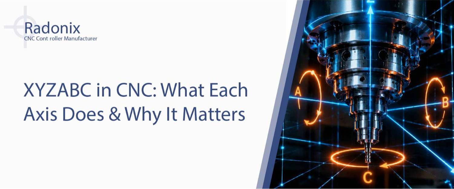
Visual diagram: all 6 CNC axes on a milling machine
Below is a detailed description of a labeled diagram that a designer can use to illustrate the full set of XYZABC axes on a vertical milling machine.
Diagram description for designer
The illustration shows a vertical CNC milling machine viewed at a three-quarter angle, so all three dimensions are clearly visible. At the center is the machine table (the flat horizontal surface where the workpiece sits) and, above it, the vertical spindle holding a cutting tool.
Three straight arrows represent the linear axes, drawn in one color (for example, blue):
- A horizontal X axis arrow runs left-to-right along the front of the table, labeled “X — left/right.”
- A horizontal Y axis arrow runs front-to-back, pointing away from the viewer, labeled “Y — forward/back.”
- A vertical Z axis arrow runs straight up and down through the spindle, labeled “Z — up/down.”
Three curved, circular arrows represent the rotary axes, drawn in a second color (for example, orange), each wrapping around its corresponding linear axis:
- An A axis curved arrow loops around the X arrow, labeled “A — rotates around X.”
- A B axis curved arrow loops around the Y arrow, labeled “B — rotates around Y.”
- A C axis curved arrow loops around the Z arrow, labeled “C — rotates around Z.”
A small origin point where the three linear arrows meet is marked “Machine Origin (0,0,0).”
Suggested caption: “The six CNC axes: X, Y, and Z move in straight lines, while A, B, and C rotate around them. Together they form the complete XYZABC motion system.”
Suggested alt-text: “Diagram of a CNC milling machine showing X, Y, Z linear axes and A, B, C rotary axes that make up the xyzabc 6-axis configuration.”
Difference between linear and rotary axes
The most fundamental distinction in the xyzabc system is between linear and rotary motion. Understanding this difference makes everything else about multi-axis machining easier to grasp.
Linear axes (X, Y, Z) move in straight lines and are measured in units of distance — millimeters or inches. When you command an X-axis move of 50 mm, the table or tool slides exactly 50 mm in that direction. Linear motion is intuitive because it matches how we naturally think about space: left, right, forward, back, up, down.
Rotary axes (A, B, C) move in circles and are measured in degrees of rotation. When you command a B-axis move of 30 degrees, the part or head tilts 30 degrees around the Y axis. Rotary motion changes the orientation of the tool or workpiece rather than its straight-line position.
Here are the key practical differences:
- Units: Linear axes use distance (mm/inch); rotary axes use angle (degrees).
- Purpose: Linear axes position the tool; rotary axes orient it.
- Hardware: Linear axes use ball screws and linear guides; rotary axes use rotary tables, trunnions, or indexers.
- Programming: Linear moves use X, Y, Z coordinates; rotary moves use A, B, C angular values.
In real machining, linear and rotary axes work together. The linear axes bring the tool to the right spot, and the rotary axes angle it correctly to reach surfaces that would otherwise be inaccessible.
Multi-axis CNC: 4-axis, 5-axis, and 6-axis explained
The number of axes a CNC machine has determines how complex the parts it can make. Adding rotary axes to the basic three linear ones unlocks progressively more capability.
3-axis CNC uses only X, Y, and Z. The tool moves in straight lines along all three directions, which is perfect for flat parts, pockets, drilling, and simple contours. It cannot tilt the tool, so undercuts and complex angled features require multiple setups.
4-axis CNC adds one rotary axis, usually the A axis (rotation around X). This lets the machine rotate the workpiece, making it ideal for machining around cylindrical parts or reaching multiple faces without re-clamping. A common example is engraving text around a tube or machining the sides of a part in one setup.
5-axis CNC adds two rotary axes (commonly A and B, or B and C) on top of the three linear axes. This is the workhorse of advanced manufacturing. The tool can approach the workpiece from virtually any angle, enabling complex shapes like turbine blades, impellers, medical implants, and aerospace components. Five-axis machining dramatically reduces setups and improves surface quality.
6-axis CNC uses the full xyzabc configuration — all three linear axes plus all three rotary axes. This offers maximum freedom of movement and is used for the most intricate geometries, simultaneous multi-side machining, and specialized industrial tasks. True 6-axis CNC machines are less common than 5-axis but excel where extreme flexibility is required.
As you move from 3 to 6 axes, programming complexity increases, but so does the range of parts you can produce in a single, accurate operation.
XYZABC in Radonix controllers: supported axis configurations
For a CNC machine to use multiple axes effectively, its motion controller must be able to coordinate all of them smoothly and in real time. Radonix CNC controllers are designed to support a range of axis configurations, from basic setups to advanced multi-axis machines.
In practice, this means a Radonix controller can manage standard 3-axis (X, Y, Z) machines as well as configurations that add rotary axes for 4-axis and 5-axis work. The controller handles the coordinated motion required when linear and rotary axes move together, which is essential for smooth multi-axis toolpaths.
Key capabilities relevant to the xyzabc axis system include:
- Support for both linear (X, Y, Z) and rotary (A, B, C) axis definitions.
- Coordinated, simultaneous multi-axis motion for complex toolpaths.
- Configurable axis assignment so the machine matches your mechanical layout.
- Real-time control to maintain accuracy across all active axes.
The right controller setup depends on your machine’s mechanical design and the type of work you do. If you’re planning a multi-axis build or upgrade, reviewing the supported axis configurations helps ensure the controller matches your needs. The goal is simply to give your machine the motion control it requires for the axes you intend to use.
Common mistakes when programming multi-axis toolpaths
Multi-axis machining is powerful, but it introduces challenges that don’t exist in simple 3-axis work. Beginners often run into the same handful of issues. Knowing them in advance saves time, tooling, and material.
- Ignoring axis direction conventions. Mixing up positive and negative directions for rotary axes is common. Always confirm which way A, B, and C rotate on your specific machine before running a program.
- Forgetting the work coordinate origin. With rotary axes, the part’s zero point can shift as it rotates. Failing to set the origin correctly leads to parts machined in the wrong location.
- Collisions and clearance errors. When the tool tilts, it can crash into clamps, fixtures, or the part itself. Always simulate multi-axis toolpaths before cutting.
- Overlooking tool length and pivot points. In 5-axis work, the relationship between tool length and the rotary pivot affects accuracy. Incorrect values cause the tool to be positioned wrong.
- Excessive rotary movement. Programming unnecessary or overly fast rotary moves can cause poor surface finish or strain the machine. Keep rotations smooth and purposeful.
- Not verifying post-processor output. The post-processor translates CAM toolpaths into machine code. A mismatched post can output the wrong axis commands, so always verify it matches your controller.
The best habit for any multi-axis programmer is to simulate first and cut second. Catching errors in software is far cheaper than crashing a tool into a fixture.
Summary table: the six CNC axes at a glance
| Axis | Motion Type | Rotation Reference | Typical Use |
| X | Linear | — | Left/right table movement; longest travel |
| Y | Linear | — | Forward/back table movement |
| Z | Linear | — | Up/down spindle movement; controls cut depth |
| A | Rotary | Rotates around X | Tilting workpiece; 4-axis cylindrical machining |
| B | Rotary | Rotates around Y | Tilting tool/head; common in 5-axis machining |
| C | Rotary | Rotates around Z | Rotating workpiece flat; turning and indexing |
Frequently Asked Questions
What does XYZABC stand for in CNC?
XYZABC refers to the six possible axes of motion on a CNC machine. X, Y, and Z are linear axes that move in straight lines, while A, B, and C are rotary axes that rotate around X, Y, and Z respectively. Together they make up a full 6-axis system.
Do I need a 5-axis or 6-axis machine for basic work?
No. For flat parts, drilling, engraving, and simple profiles, a standard 3-axis machine using only X, Y, and Z is perfectly sufficient. Rotary axes become useful only when you need to machine multiple sides or complex angled surfaces.
What’s the difference between A, B, and C axes?
They are all rotary axes, but each rotates around a different linear axis. The A axis rotates around X, the B axis rotates around Y, and the C axis rotates around Z. The one you use depends on your machine’s design and the part orientation you need.
Is more axes always better?
Not necessarily. More axes mean greater capability but also higher cost and more complex programming. The best choice is the number of axes that matches the parts you make. Many shops do excellent work with 3-axis and 4-axis machines.
Conclusion
The xyzabc axis system is the language of CNC motion. Once you understand that X, Y, and Z handle straight-line positioning while A, B, and C add rotation, the whole world of multi-axis machining starts to make sense. Whether you’re running a simple 3-axis mill or planning a full 6-axis build, knowing what each axis does — and how they work together — is essential to programming accurate, efficient toolpaths. Start with the fundamentals, simulate before you cut, and let your understanding of the axes guide every project you take on.