
A single glitch in your CNC Machine Control Unit can halt production for hours, costing throughput, scrap, and sanity. In 2025, machine reliability and cycle-time consistency hinge on a well-specified, properly configured control core.
This guide breaks down the CNC Machine Control Unit from the ground up—components, wiring, software, calibration, and troubleshooting—so you can deploy fast, cut accurately, and keep spindles turning.
We’ll cover CNC unit basics, compare CNC controller types (Fanuc control unit, Siemens CNC controller, and open architectures), and walk you through a practical setup checklist.
You’ll also learn how to integrate your control with Radonix CNC controllers, add IoT connectivity for predictive maintenance, and leverage edge computing for real-time analytics.
If you want a deeper primer on HMI and programming, browse the Radonix blog starting with How CNC Controller Works: Full Guide to Precision Control.
Understanding the CNC Machine Control Unit: Role and Evolution
The CNC Machine Control Unit is the command center that interprets programs, synchronizes motion, and supervises safety. Early systems read punch cards and tape; today’s industrial CNC control systems run multi-core processors with deterministic fieldbuses, real-time kernels, and built-in diagnostics.
At its core, the CNC Machine Control Unit performs four essential jobs (CNC unit basics):
- Interprets G-code and M-code, manages modal states, and plans motion profiles.
- Coordinates multi-axis interpolation with servo drive control and feedback loops.
- Interfaces with I/O for sensors, probes, tool changers, and coolant systems.
- Presents CNC control panel functions (HMI) for setup, overrides, alarms, and diagnostics.
Why it matters in practice:
- Precision: Smooth micro-interpolation and fast look-ahead stabilize feed rates in tight geometry.
- Uptime: Robust PLC integration in CNC catches faults, protects hardware, and shortens recovery time.
- Scalability: From a 3-axis router to a 5-axis mill-turn, the same CNC Machine Control Unit architecture scales via firmware options and modules.
For a control-panel overview, see: What Is a CNC Control Panel? Complete Guide 2025 on the Radonix blog.
Key Components of a CNC Machine Control Unit
Knowing what’s inside your controller helps you specify the right hardware, budget accurately, and troubleshoot with confidence. The list below highlights typical modules you’ll find in a CNC Machine Control Unit used in industrial CNC control systems.
- CPU/processor and real-time OS
- Memory (RAM/ROM/flash)
- Motion controller (multi-axis interpolation)
- Drive interfaces and feedback (encoders, resolvers)
- I/O modules and PLC layer
- Power supply, UPS, and grounding
- HMI and CNC control panel functions
- Networking and fieldbuses (EtherCAT, Profinet, CANopen)
- Data storage and logging
| Component | Function | Common Types / Notes |
| CPU / SoC | Real-time motion planning and program execution | x86, ARM; real-time Linux or RTOS; multi-core for look-ahead |
| Memory (RAM/ROM/Flash) | Buffer programs, store parameters, firmware | ECC RAM for reliability; separate flash for parameters |
| Motion Controller | Interpolates axes; jerk/acceleration control | Integrated or separate card; supports 3–12+ axes |
| Drive Interfaces | Command to servo drives (step/dir, analog, bus) | EtherCAT, SERCOS, Mechatrolink; tight sync for servo drive control |
| Feedback Inputs | Position/velocity feedback | Incremental/absolute encoders, resolvers, dual-loop options |
| PLC / I/O | Machine sequencing and interlocks | Onboard PLC (IEC 61131-3); digital/analog I/O; safety I/O |
| Power System | Stable DC rails and backup | 24 VDC logic; line filters; UPS for safe shutdown |
| HMI / Panel | Operation, setup, diagnostics | Touchscreen + hard keys; jog, feed/spindle overrides |
| Networking | Plant integration, remote support | Ethernet, OPC UA/MTConnect, Wi‑Fi for diagnostics |
| Storage | Program and log retention | SD/SSD; rolling logs for predictive maintenance |
Notes:
- Fanuc control unit and Siemens CNC controller families bundle motion + PLC tightly; open systems split functions for flexibility.
- For integration details and controller selection, explore Radonix CNC controllers.
Step-by-Step Setup Essentials for CNC Machine Control Unit
A reliable setup is equal parts clean wiring, correct software configuration, and methodical calibration. Follow this field-tested workflow when bringing up a CNC Machine Control Unit—new or retrofit.
Hardware installation
- Mount the controller in a ventilated electrical cabinet with an appropriate IP rating.
- Isolate power rails: drives vs. logic. Add surge protection and EMI line filters.
- Provide grounding and bonding points per manufacturer specs.
Wiring and connections
- Power: Separate feeds for drives, control logic, and HMI. Verify voltage and polarity.
- Motors/encoders: Route motor power separately from signal cables to reduce noise.
- I/O and PLC: Wire e-stop chain, door interlocks, lube pumps, coolant, and probes. Label everything.
- Fieldbus: Connect EtherCAT/Profinet segments with shielded cables; terminate correctly.
- Networking: Provide a dedicated, VLAN-segmented Ethernet port for the CNC Machine Control Unit.
Software loading and configuration
- Firmware: Load correct controller firmware and options for axes, spindles, and cycles.
- Parameters: Configure machine travel limits, ballscrew pitch, encoder scale, gear ratios, and motor poles.
- Drives: Set servo tuning basics (current/velocity loops), homing sequence, and torque limits.
- CAD/CAM posts: Install verified post-processors for your control; map M-codes and cycles.
- HMI: Customize CNC control panel functions—soft keys, macro buttons, probe routines.
Calibration and testing
- Homing: Verify repeatability; adjust switch offsets and latch distances.
- Axis calibration: Use a laser interferometer or ballbar (ISO 230-1) for scale and backlash compensation.
- Spindle: Check runout, orientation, and speed accuracy.
- Safety: Validate the e-stop chain, door interlocks, and light curtains.
- Cut test: Start with air moves, then a light facing pass to confirm feeds, directions, and coolant logic.
ASCII wiring topology reference diagram
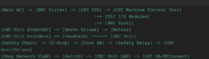
Table: Setup checklist and verification
| Step | Task | Tools | Pass/Fail Criteria |
| Power-up | Verify voltages and grounding | DMM, insulation tester | Rails within spec; no leakage; stable ground |
| Motion | Jog each axis safely | HMI jog, handwheel | No faults; correct direction; smooth motion |
| Homing | Set and test home routine | HMI homing | Repeatability within spec; switches debounce |
| Scaling | Calibrate axis distances | Laser, dial indicator | Error < target (e.g., <5 µm/300 mm) |
| Drives | Tune servo loops | Drive tool, oscilloscope | Minimal following error; stable response |
| Safety | Validate e-stop chain | Safety tester | Category level met; immediate power removal |
| Programs | Run sample cycles | CAM post, test part | Dimensions within tolerance; no alarms |
Pro tip: Keep a dated setup log tied to the CNC Machine Control Unit serial number. It speeds future troubleshooting and audits. For hardware and I/O specifics, see the Radonix CNC Control Board and the Radonix CNC controllers lineup.
Troubleshooting and Maintenance for CNC Control Units
Even a well-built CNC Machine Control Unit will throw alarms now and then. A disciplined approach and the right CNC control panel functions turn hours of guesswork into minutes of diagnosis.
Common symptoms and quick fixes
- Overheating or random resets
- Check cabinet airflow, clean filters, and ensure ambient temperature is within spec.
- Inspect power rails for droop under load; validate UPS health.
- Electrical noise and encoder glitches
- Separate power and signal routing; add ferrites; improve shielding/grounding at one end only.
- Lower input thresholds or enable encoder noise filters if supported.
- Following error/chatter
- Retune velocity/position loops; confirm ballscrew preload and way lubrication.
- Reduce acceleration/jerk in motion parameters.
- I/O or PLC anomalies
- Review PLC integration in CNC: check ladder logic for rung conditions and interlocks.
- Use I/O monitor pages to confirm sensor transitions in real time.
- Communication faults (fieldbus)
- Verify cable integrity and termination; check bus scan lists and node IDs.
- Ensure firmware compatibility across drives and the CNC Machine Control Unit.
- E-stop or safety trips
- Test safety relay and feedback loops; check door switches and light curtains for bounce.
- Validate that the safety channel drops drive power as designed.
Leverage your HMI
- Use diagnostics, alarm history, and trace/oscilloscope tools built into many HMIs.
- The most useful CNC control panel functions during faults: I/O status, axis following error graphs, fieldbus topology view, temperature/voltage monitors, and macro variable watch lists.
Maintenance cadence
- Quarterly: Cabinet cleaning, fan inspection, backup parameters, and firmware notes.
- Semiannual: Drive tuning check, encoder battery/absolute position validation, power quality audit.
- Annual: Full ISO 230-1 motion audit and ballbar test; refresh thermal compensation maps.
For a systematic diagnostic routine, review How CNC Controller Works: Full Guide to Precision Control on the Radonix blog.
2025 Trends: Smart Upgrades for CNC Machine Control Units
Smart shops are upgrading the CNC Machine Control Unit with edge analytics and connected services that shorten diagnosis time and prevent failures.
What’s new and useful
- Edge computing at the controller
- Real-time anomaly detection on the following error, temperature, and spindle load.
- On-device AI models suggest feed/speed adjustments before chatter begins.
- IoT connectivity for predictive maintenance
- OPC UA or MTConnect streams to dashboards, automatic alerting, and service tickets.
- Wear models for spindle bearings and ball screws based on duty cycle and vibration data.
- Smarter networks and security
- Time-Sensitive Networking (TSN) improves deterministic Ethernet.
- Zero-trust device identity and signed firmware reduce tampering risks.
How Radonix helps
- Radonix CNC controllers offer edge-ready processing, OPC UA/MTConnect connectors, and macro-friendly HMIs to embed your diagnostics.
- Seamless drop-in with common CNC controller types and fieldbuses means faster retrofits and fewer surprises.
Explore controller selection and modernization paths here: Radonix CNC controllers and Types of Controllers in CNC Machines Explained.
Conclusion: Specify, Set Up, and Sustain for Peak Throughput
Getting the CNC Machine Control Unit right pays dividends in precision, uptime, and operator confidence. Understand the architecture, select the right CNC controller types, wire cleanly, and validate with disciplined calibration.
Use your CNC control panel functions to see inside the machine—then apply proactive maintenance and 2025-ready upgrades like edge analytics and IoT.
If your shop needs to modernize, pair a capable CNC Machine Control Unit with robust motion and diagnostics from Radonix. You’ll accelerate setup, stabilize cycles, and grow capacity without growing headaches.
Upgrade your CNC machine control unit with Radonix—Visit Radonix Today
FAQ
Q1: What are the main CNC controller types?
A: The big categories are proprietary (e.g., Fanuc control unit, Siemens CNC controller), PC-based/open systems running real-time OS, and hybrid controls with integrated PLCs. Consider axis count, fieldbus support, macro capability, service availability, and how they fit your CNC Machine Control Unit retrofit timeline.
Q2: How does PLC integration in CNC improve reliability?
A: PLC integration in CNC handles sequencing, safety interlocks, and machine I/O deterministically. It offloads logic from the CNC Machine Control Unit motion planner, simplifies diagnostics via ladder views, and prevents unsafe conditions, improving uptime and making troubleshooting more transparent.
Q3: Which CNC control panel functions are most useful for setup?
A: I/O monitor, axis following error plots, fieldbus diagnostics, offsets/tool tables, and alarm history are essential. These cnc control panel functions help you verify wiring, tune servo drive control, and catch parameter mistakes quickly when commissioning a CNC Machine Control Unit.
Q4: What’s the safest way to wire drives and encoders?
A: Separate motor power and encoder/signal routing; use shielded twisted pairs with single-point grounding. Keep power supplies isolated (logic vs. drives) and verify terminations on your fieldbus. Document everything—future service on the CNC Machine Control Unit depends on clear labels.
Q5: How do I choose between different industrial CNC control systems?
A: Match capabilities to part mix and growth: axes/spindles, look-ahead performance, macro support, fieldbus options, and ecosystem (service, posts, training). Evaluate TCO and retrofit complexity. The CNC Machine Control Unit should integrate cleanly with your existing drives and sensors.
Q6: When should I add IoT and edge analytics?
A: If downtime costs are significant or you run lights-out, add IoT/edge now. Start with streaming alarms and spindle/axis loads from the CNC Machine Control Unit via OPC UA/MTConnect. Then layer predictive models for bearings, ballscrews, and thermal drift to avoid unplanned stops.
Contact Us:
- E-Mail: info@radonix.com
- Phone: +90 (553) 920 5500